Create the rover's model
This article belongs to the series “Create Sphero RVR+ simulation model” and will walk you through the essential steps to create the rover’s model.
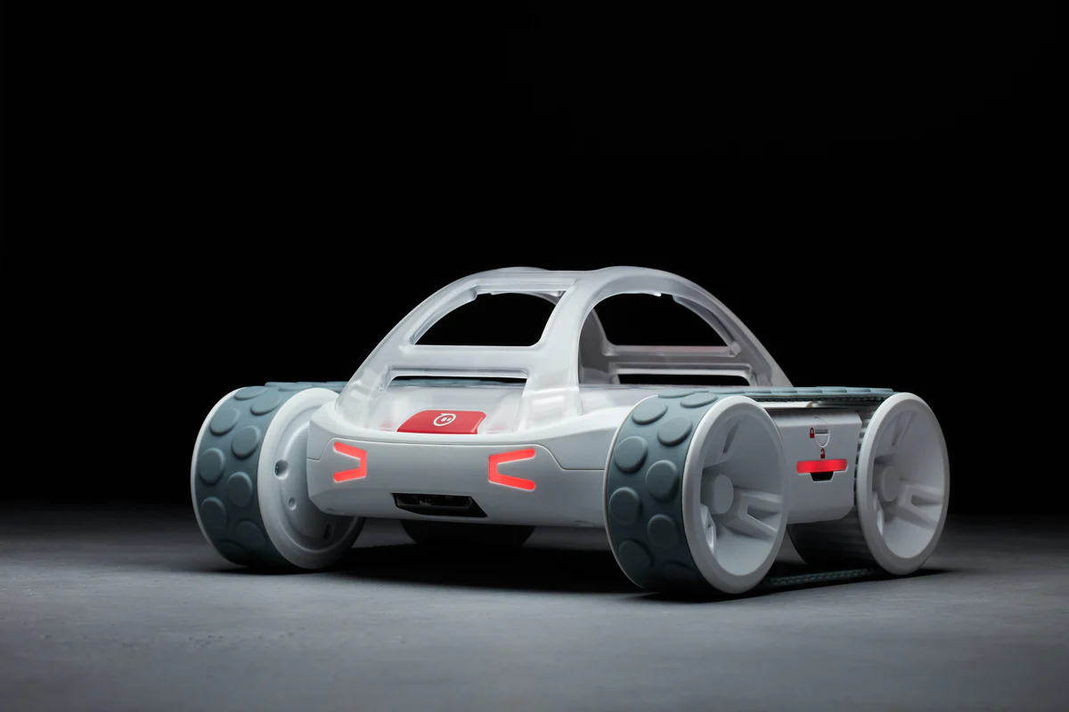
Source: https://sphero.com/blogs/press-releases/sphero-announces-rvr-plus
To avoid confusion, I will refer the Sphero RVR+ robot as smply the “rover” for the remainder of this article.
Let’s combine the different parts of the rover into a single model
First of all, big shout out to the Information institutte of Department of Computer Science of University of Innsbruck | Universität Innsbruck for providing their implementation of modeling and, most importantly, the meshes of the rover, as its CAD should not be publicly released by its manufacturer due to the fafct that the rover is a final product and not just any upper-stream component such as sensors and motors. In the same vein, I also claim my disclaimer here that the usage of the rover’s simulation model hereby is for hobby only and therefore is not involved anyhow in any commercial or lucrative purpose nor incentive. You can find their implementation here: ros-sphero-rvr/sphero_rvr_description.
Despite the fact that the final model from the mentioned repository may appear to be a rough CAD sketch of the actual rover, it is good enoguh for any posterior evaluations.
Create a new ROS 2 description package
As usual, if you have not created any ROS 2 package to hold the details of the model, let’s do it now:
cd <path/to/your>/ros2_ws/src
ros2 pkg create --build-type ament_cmake sphero_rvr_description
cd ..
colcon build --packages-select sphero_rvr_description
source ~/.bashrc # or
source $HOME/ros2_ws/install/setup.bash # to make sure that ROS 2 sources to your current workspace
You created a new package sphero_rvr_description and build it and making sure that the ROS file system can determine where the package is.
Now head back to the new package, let’s create three directories and have CMake to install them when building the package:
# Assume you are under the root directory of the ROS 2 workspace
cd src/sphero_rvr_description

mkdir model
mkdir meshes
mkdir launch
Open the CMakeLists.txt and add the following line in it:
install(
  DIRECTORY launch meshes model
  DESTINATION share/${PROJECT_NAME}
)
Now head to the root directory of the workspace and build the package again. Once this is done, let’s add the corresponding URDF under model/ directory and the corresponding STL files. Yes, we will have STL file for the wheels and body of the robot.
The texture color definitions
Before moving on to creating the URDF file for the main body, let’s add a materials.urdf to define the color of the different meshes. Create the file:
touch materials.urdf
Open the file with your favorite IDE or text editor and paste the following content:
<?xml version="1.0"?>
<robot>
  <material name="SpheroRVR/White">
    <color rgba="1 1 1 1.0"/>
  </material>

  <material name="SpheroRVR/DarkGrey">
    <color rgba="0.3 0.3 0.3 1.0"/>
  </material>

  <material name="SpheroRVR/LightGrey">
    <color rgba="0.8 0.8 0.8 1.0"/>
  </material>

  <material name="SpheroRVR/Black">
    <color rgba="0 0 0 1.0"/>
  </material>

  <material name="SpheroRVR/Grey">
    <color rgba="0.7 0.7 0.7 1.0"/>
  </material>

  <material name="SpheroRVR/Blue">
    <color rgba="0.0 0.0 0.8 1.0"/>
  </material>

</robot>
These material elements define the different colors in their corresponding RGB codes.
Curate the meshes
Now under the meshes/ directory, place all the necessary STL files. You can download these files under ros-sphero-rvr/sphero_rvr_description under the meshes/ directory. These STL files are:
- Sphero_Base.stl
- Sphero_Wheel.stl
- Sphero_Wheel_L.stl
- Sphero_Wheel_R.stl
- unilidar_l1_mesh.stl
Make sure you place all these files under your own meshes/ directory. Perfect! Now we are ready to move on to the main URDF file.
THe main body or the chasis of the rover
The first stop is to define the robot’s body or its chasis. First, creat the URDF file under the model/ directory, where you already created the materials.urdf file:
cd model/
touch sphero_rvr.urdf.xacro
Open this URDF file with your favorite editor, paste the following content in it:
<?xml version="1.0"?>
<robot name="Sphero_RVR+" xmlns:xacro="http://ros.org/wiki/xacro">

  <xacro:include filename="$(find sphero_rvr_description)/model/materials.urdf"/>

  <xacro:property name="robotname" value="Sphero_RVR+" />
  <xacro:property name="mesh_dir" value="meshes" />

  <xacro:property name="M_PI" value="3.1415926535897931" />
  <xacro:property name="velocity_scale_factor" value="1.0"/>
  <xacro:property name="mm_to_m" value="0.001"/>
  <xacro:property name="mm2_to_m2" value="0.001"/>
  <xacro:property name="gr_to_Kg" value="0.001"/>
  <xacro:property name="negligible_mass" value="${200*gr_to_Kg}"/>

  <link name="${robotname}_base_link">
    <inertia ixx="${negligible_mass * 100 * mm2_to_m2}" ixy="0.0" ixz="0.0"
            iyy="${negligible_mass * 100 * mm2_to_m2}" iyz="0.0" izz="${negligible_mass * 100 * mm2_to_m2}"
    />
    <visual>
      <origin xyz="-0.017 -0.101 0.017" rpy="0 0 0"/>
      <geometry>
        <mesh filename="package://sphero_rvr_description/meshes/Sphero_Base.stl" scale="0.001 0.001 0.001" />
      </geometry>
      <material name="SpheroRVR/White"/>
    </visual>
    <collision>
      <origin xyz="0.0 0.0 0.04" rpy="0 0 0"/>
      <geometry>
        <box size="0.2 0.13 0.06"/>
      </geometry>
    </collision>
  </link>
</robot>
As you can see, the color file materials.urdf is already included and we can directly access the various colors defined in that file. The robotname as a property is already set to be Sphero_RVR+ but you can name it whatever you please.
The chasis is treated as a link, which is a node of reference frame in the whole TF tree, and it will be later associated to the global frame in the form of map --> odom --> ${robotname}_base_link. From here on for expression simplicity and consistency, instead of calling it as ${robotname}_base_link I will simply put it as base_link.
In the Turtlebot literature, you will also often encounter that in between the odom and base_link there is an extra TF frame called base_footprint and is assigned to be on the ground directly underneath the robot’s chasis. This is just an optional convention and would not affect the analysis of spatial transformation down the road.
The wheels of the rover
Now I’ll exemplify how to add a single wheel to show the syntax mechanism of relating from one link to another. This grants you the advantage to assemble a robot from different URDF files of the components. We will also adopt this approach in later article to put our robot and sensors together as a whole.
So, let’s start with the front-left wheel:
<!-- Left Front Wheel -->
  <joint name="${robotname}_wheel_fl_joint" type="fixed">
    <origin xyz="0.059 0.09 0.03" rpy="0 90 0"/>
    <axis xyz="0 1 0"/>
    <limit effort="30" velocity="1.0" />
    <safety_controller k_velocity="10" k_position="15"  />
    <dynamics friction="1.0" damping="1.0"/>
    <parent link="${robotname}_base_link"/>
    <child link="${robotname}_wheel_fl_link"/>
  </joint>

  <link name="${robotname}_wheel_fl_link">
    <inertia ixx="${negligible_mass * 100 * mm2_to_m2}" ixy="0.0" ixz="0.0"
            iyy="${negligible_mass * 100 * mm2_to_m2}" iyz="0.0" izz="${negligible_mass * 100 * mm2_to_m2}"
    />
    <visual>
      <origin xyz="-0.042 0 -0.033" rpy="0 0 0"/>
      <geometry>
        <mesh filename="package://sphero_rvr_description/meshes/Sphero_Wheel_L.stl" scale="0.001 0.001 0.001" />
      </geometry>
      <material name="SpheroRVR/White"/>
    </visual>
    <collision>
      <origin xyz="0.0 0 0.0" rpy="${M_PI/2} 0 0"/>
      <geometry>
        <cylinder radius="0.033" length="0.03"/>
      </geometry>
    </collision>
  </link>
As we can see here, the order in which the join and link are defined does not matter. The joint element defines the spatial relationship from one parent link or frame to the child. The link, on the other hand, defines the TF frame’s physical and visual properties.
The definition for the rest of the wheels follows the same pattern. The whole URDF script should become as following:
<?xml version="1.0"?>
<robot name="Sphero_RVR+" xmlns:xacro="http://ros.org/wiki/xacro">

  <xacro:include filename="$(find sphero_rvr_description)/model/materials.urdf"/>

  <xacro:property name="robotname" value="Sphero_RVR+" />
  <xacro:property name="mesh_dir" value="meshes" />

  <xacro:property name="M_PI" value="3.1415926535897931" />
  <xacro:property name="velocity_scale_factor" value="1.0"/>
  <xacro:property name="mm_to_m" value="0.001"/>
  <xacro:property name="mm2_to_m2" value="0.001"/>
  <xacro:property name="gr_to_Kg" value="0.001"/>
  <xacro:property name="negligible_mass" value="${200*gr_to_Kg}"/>

  <link name="${robotname}_base_link">
    <inertia ixx="${negligible_mass * 100 * mm2_to_m2}" ixy="0.0" ixz="0.0"
            iyy="${negligible_mass * 100 * mm2_to_m2}" iyz="0.0" izz="${negligible_mass * 100 * mm2_to_m2}"
    />
    <visual>
      <origin xyz="-0.017 -0.101 0.017" rpy="0 0 0"/>
      <geometry>
        <mesh filename="package://sphero_rvr_description/meshes/Sphero_Base.stl" scale="0.001 0.001 0.001" />
      </geometry>
      <material name="SpheroRVR/White"/>
    </visual>
    <collision>
      <origin xyz="0.0 0.0 0.04" rpy="0 0 0"/>
      <geometry>
        <box size="0.2 0.13 0.06"/>
      </geometry>
    </collision>
  </link>

  <!-- Left Front/Rear Wheel -->
  <joint name="${robotname}_wheel_fl_joint" type="fixed">
    <origin xyz="0.059 0.09 0.03" rpy="0 90 0"/>
    <axis xyz="0 1 0"/>
    <limit effort="30" velocity="1.0" />
    <safety_controller k_velocity="10" k_position="15"  />
    <dynamics friction="1.0" damping="1.0"/>
    <parent link="${robotname}_base_link"/>
    <child link="${robotname}_wheel_fl_link"/>
  </joint>

  <joint name="${robotname}_wheel_rl_joint" type="fixed">
    <origin xyz="-0.059 0.09 0.03" rpy="0 0 0"/>
    <mimic joint="${robotname}_wheel_fl_joint" multiplier="1" offset="0" />
    <axis xyz="0 1 0"/>
    <limit effort="30" velocity="1.0" />
    <safety_controller k_velocity="10" k_position="15"  />
    <dynamics friction="1.0" damping="1.0"/>
    <parent link="${robotname}_base_link"/>
    <child link="${robotname}_wheel_rl_link"/>
  </joint>

  <link name="${robotname}_wheel_fl_link">
    <inertia ixx="${negligible_mass * 100 * mm2_to_m2}" ixy="0.0" ixz="0.0"
            iyy="${negligible_mass * 100 * mm2_to_m2}" iyz="0.0" izz="${negligible_mass * 100 * mm2_to_m2}"
    />
    <visual>
      <origin xyz="-0.042 0 -0.033" rpy="0 0 0"/>
      <geometry>
        <mesh filename="package://sphero_rvr_description/meshes/Sphero_Wheel_L.stl" scale="0.001 0.001 0.001" />
      </geometry>
      <material name="SpheroRVR/White"/>
    </visual>
    <collision>
      <origin xyz="0.0 0 0.0" rpy="${M_PI/2} 0 0"/>
      <geometry>
        <cylinder radius="0.033" length="0.03"/>
      </geometry>
    </collision>
  </link>

  <link name="${robotname}_wheel_rl_link">
    <inertia ixx="${negligible_mass * 100 * mm2_to_m2}" ixy="0.0" ixz="0.0"
            iyy="${negligible_mass * 100 * mm2_to_m2}" iyz="0.0" izz="${negligible_mass * 100 * mm2_to_m2}"
    />
    <visual>
      <origin xyz="-0.042 0 -0.033" rpy="0 0 0"/>
      <geometry>
        <mesh filename="package://sphero_rvr_description/meshes/Sphero_Wheel_L.stl" scale="0.001 0.001 0.001" />
      </geometry>
      <material name="SpheroRVR/White"/>
    </visual>
    <collision>
      <origin xyz="0.0 0 0.0" rpy="${M_PI/2} 0 0"/>
      <geometry>
        <cylinder radius="0.033" length="0.03"/>
      </geometry>
    </collision>
  </link>


  <!-- Right Front/Rear Wheel -->
  <joint name="${robotname}_wheel_fr_joint" type="fixed">
    <origin xyz="0.059 -0.09 0.03" rpy="0 90 0"/>
    <axis xyz="0 1 0"/>
    <limit effort="30" velocity="1.0" />
    <safety_controller k_velocity="10" k_position="15"  />
    <dynamics friction="1.0" damping="1.0"/>
    <parent link="${robotname}_base_link"/>
    <child link="${robotname}_wheel_fr_link"/>
  </joint>

  <joint name="${robotname}_wheel_rr_joint" type="fixed">
    <origin xyz="-0.059 -0.09 0.03" rpy="0 0 0"/>
    <mimic joint="${robotname}_wheel_fr_joint" multiplier="1" offset="0" />
    <axis xyz="0 1 0"/>
    <limit effort="30" velocity="1.0" />
    <safety_controller k_velocity="10" k_position="15"  />
    <dynamics friction="1.0" damping="1.0"/>
    <parent link="${robotname}_base_link"/>
    <child link="${robotname}_wheel_rr_link"/>
  </joint>

  <link name="${robotname}_wheel_fr_link">
    <inertia ixx="${negligible_mass * 100 * mm2_to_m2}" ixy="0.0" ixz="0.0"
            iyy="${negligible_mass * 100 * mm2_to_m2}" iyz="0.0" izz="${negligible_mass * 100 * mm2_to_m2}"
    />
    <visual>
      <origin xyz="-0.042 0 -0.033" rpy="0 0 0"/>
      <geometry>
          <mesh filename="package://sphero_rvr_description/meshes/Sphero_Wheel_R.stl" scale="0.001 0.001 0.001" />
      </geometry>
      <material name="SpheroRVR/White"/>
    </visual>
    <collision>
      <origin xyz="0.0 0 0.0" rpy="${M_PI/2} 0 0"/>
      <geometry>
        <cylinder radius="0.033" length="0.03"/>
      </geometry>
    </collision>
  </link>

  <link name="${robotname}_wheel_rr_link">
    <inertia ixx="${negligible_mass * 100 * mm2_to_m2}" ixy="0.0" ixz="0.0"
            iyy="${negligible_mass * 100 * mm2_to_m2}" iyz="0.0" izz="${negligible_mass * 100 * mm2_to_m2}"
    />
    <visual>
      <origin xyz="-0.042 0 -0.033" rpy="0 0 0"/>
      <geometry>
          <mesh filename="package://sphero_rvr_description/meshes/Sphero_Wheel_R.stl" scale="0.001 0.001 0.001" />
      </geometry>
      <material name="SpheroRVR/White"/>
    </visual>
    <collision>
      <origin xyz="0.0 0 0.0" rpy="${M_PI/2} 0 0"/>
      <geometry>
        <cylinder radius="0.033" length="0.03"/>
      </geometry>
    </collision>
  </link>

</robot>
You have the four wheels associated with the chasis. From here, you can also describe how the wheels spin but I will leave such task to your increasingly able hands.
Launch file to load in the model to robot_state_publisher and joint_state_publisher
Let’s not forget about the launch file although you can bring up all the necessary nodes one-by-one.Please create a new launch file if you have not done so: sphero_rrvr_model.launch.py and paste the following in it:
#!/usr/bin/env python3

from pathlib import Path
from launch import LaunchDescription
from launch.substitutions import Command
from launch_ros.actions import Node
from launch_ros.substitutions import FindPackageShare

def generate_launch_description():
    pkg_path = FindPackageShare('sphero_rvr_description').find('sphero_rvr_description')
    urdf_dir: Path = Path(pkg_path) / 'model'
    xacro_file_path = str( urdf_dir / 'sphero_rvr.urdf.xacro' )
    rviz_config_path = str( Path(pkg_path) / 'launch' / 'single_robot_test_view.rviz' )

    assert Path(xacro_file_path).exists(), f'URDF file not found at {xacro_file_path}'
    assert Path(xacro_file_path).is_file(), f'URDF file {xacro_file_path} is NOT a file'

    return LaunchDescription([
        # Robot State Publisher Node
        Node(
            package='robot_state_publisher',
            executable='robot_state_publisher',
            name='robot_state_publisher',
            output='screen',
            parameters=[{'robot_description': Command(['xacro ', xacro_file_path])}],
            arguments=[xacro_file_path]
        ),
        Node(
            package='joint_state_publisher',
            executable='joint_state_publisher',
            name='joint_state_publisher'
        ),
        Node(
            package='rviz2',
            executable='rviz2',
            name='rviz2',
            output='screen',
            arguments=['-d', rviz_config_path]
        )
    ])
Here we simply have a list of nodes passed in LaunchDescription and return it under the function generate_launch_description.
Here you may have already discovered that I defined a rviz_config_path and it is fed into Rviz2 as such:
  Node(
      package='rviz2',
      executable='rviz2',
      name='rviz2',
      output='screen',
      arguments=['-d', rviz_config_path]
  )
in the form of
arguments=['-d', rviz_config_path]
which is equivalent to the command:
rviz2 -d {whatever/path/to/your/rviz_config}.rviz
Of course, replace the argument above with your actual Rviz2 configuration file.
Conclusion
In this article, we go through the major steps to assemble the different parts of the robot into a whole. Next stop, mount all the sensors and other housing structure onto the rover.