Create Sphero RVR+ simulation model
Where are we? Why and how to simulate our robot from scratch?
Now as you have purchased the sensors, the development kit, the battery, and, most importantly, your robot rover / mobile platform, what should you do to “port” it into the virtual world to either visualize the robot model or do some serious simulation with it? After all you cannot develop the algorithms on top of something that is barely depicted in the virtual world.
Fear not, ROS 2 got you covered with its own reference systems and visualization kits. Let’s find out how to develop your robot model from scratch.
The scope of this article
In this article we will limit our discussion to the following:
- All within ROS 2 eco-system
- Basic definitions of the key terminologies so we are on the same page
- The major steps that you will take and why
- Walk you through the setup
And no worries, you do not need to equip with ample knowledge of CAD drawing, though it would become helpful for future cases in which you want to draw the components yourself.
What alternatives are there?
There are major robot and sensor makers that provide their off-the-shelf ROS2 description packages so you can simply plug-and-play to display the simulation model in Rviz 2 and whatever simulator you picked. But we are diving into the “unfortunate” case where we need to device everything from scratch on our own.
Speaking of simulators, there are some open-source options available to choose from:
- Gazebo (Soon to be deprecated)
- Webots: Very beginner-friendly
- Ignition Gazebo: This is the disstribution compatible to ROS 2 Humble and beyond
- Unity
- CoppeliaSim (formerly V-REP): Need to use an interface plugin to run CoppeliaSim with ROS 2: simROS2
Lightweight alternatives
- stage_ros2: a 2D robot simulator
- simple_pybullet_ros2: Supported up to ROS 2 Foxy
Specialized frarmeworks
- Orca4: a set of ROS2 packages that provide basic AUV (Autonomous Underwater Vehicle) functionality for the BlueRobotics BlueROV2. Orca4 runs in Gazebo Harmonic.
The major next steps
To build a robot model to ease in reference frame conversion and rboot model visualization, you will take the following steps:
- Build up the robot’s reference system consisting of different joints and links to associate its various components
- Find the component’s meshes from different online or offline sources
- Create ROS 2 descrption package for each components
- Use xacro to specify the components’ models with URDF scripts. Load the script into robot_state_publisher and aided with joint_state_publisher to render the 3D model
- Put the components together to form the final robot form factor
- Render the model in Rviz 2
I will refer to my actual robot’s model building as the example throughout this article.
What is a TF tree? Why do we need it?
Source: tf - ROS Wiki
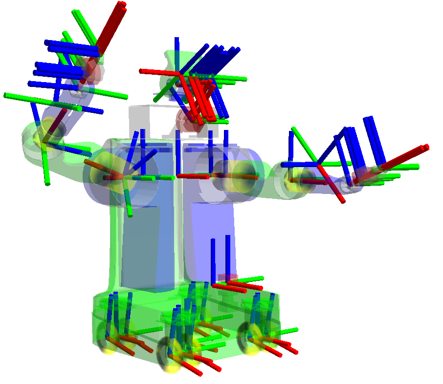
In robotics, the concept of reference frames from the world to a link on the robot’s body is the most essential part of control. Without this concept, the robot will be unable to determine where are its different copmponents, let alone determining where is it relative to its surrouding. Fortunately, roboticicsts had devised the reference frames based on the joint and links on a robot to monitor the positions of each of its parts. But we are talking about a rover! You may exclaimed. Definitely, the robot we are discussing in this article lacks any limbs or head whatsoever, but its wheels, the sensors sticking out of its back are all considered as its “limbs” defined with joint and links. To keep track of where the different parts of a robot is at in any arbitrary time is not a trivial task in itself, let alone estimating the pose within the world.
Fortunately, the ROS community had implemented the tf2 libraries to automatically calculate the different joints and links of the robot so the developper does not have to, the ROS developers refer the data structure to hold the different robot’s components as TF Tree. A TF Tree is a hierarhial structure that represents the relationship between different coordinate frame in a robot system. It is crucial for managing spatial transformations, which later we will see, are essentials for robot navigation, sensor data processing, and oerall system coordination. But why does it have to be a tree and not a graph? If we regard each joint on the robot body as a node linked up by links which are the edges, since the whole tree starts from a single world frame, and from there to derive the different robot with a unique chasis and from there the corresponding joints, we get an acyclic graph or tree. The TF2 imposes that a child node can only be derived from one parent node and that one parent node can possesses multiple child nodes and not the other way around. The abstraction saves the roboticists much headache and make the robot body coordinate clearer not only in a single robot scenario, but multi-robot relative to the world.
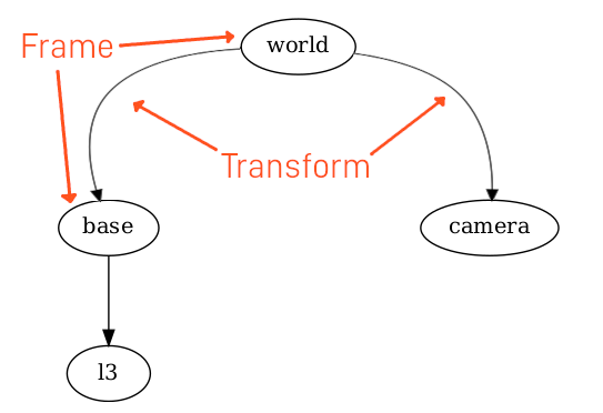
Source: The Transform System (tf2)
I found a well-written article “The Transform System (tf2)” that can help you better understand what roles TF2 plays in the spatial transformations, especially in the ROS 2 eco-ssytem.
What should our robot’s TF tree look like?
The robot that I assembled consists of the following components:
- Robot rover
- 4 wheels
- the chasis
- The mounted housing (can be neglected for this article’s discussion)
- 1 x stereo camera
- 1 x 3D LiDAR
As we are concerned with sensor data collection, the pose estimation of the whole robot, I am bypassing the development kit and the power sstation as it is not relevant for our spatial transformation analysis.
With the above list, our TF tree is shown in the following figure:
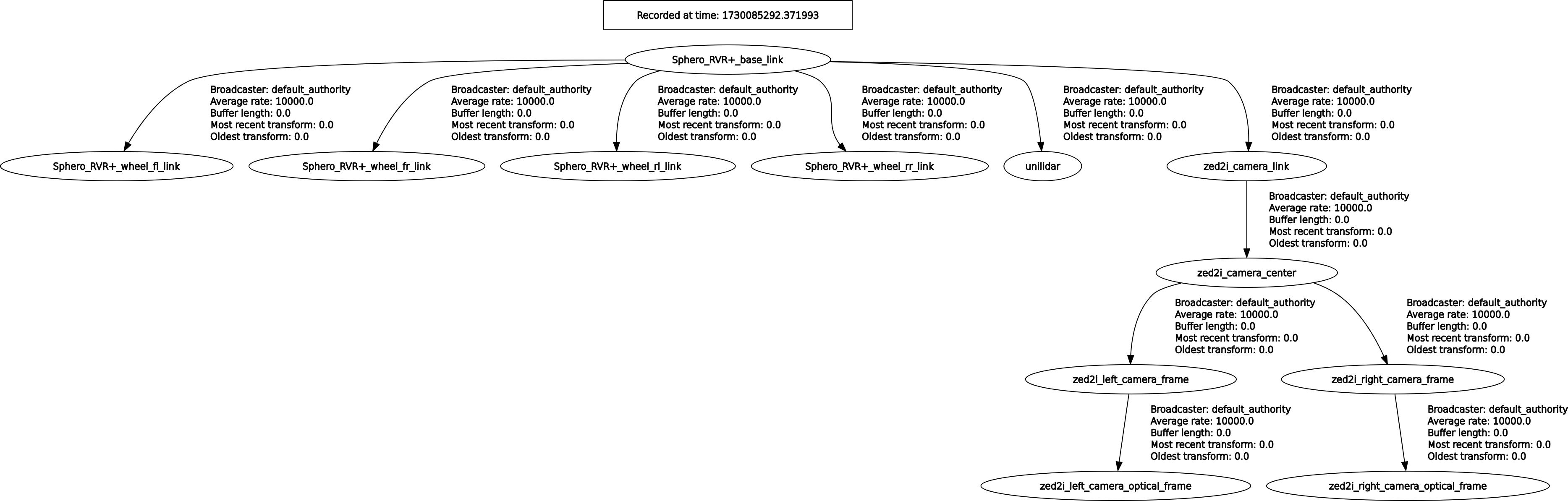
As the robot can not yet estimate its relative pose within the world frame, it is missing the “map” and “odom” frames in its tree. We will later learn what are the defintions of these two reference frames, what they mean to the robot, and how we can add them into the TF tree.
What is robot_state_publisher and joint_state_publisher?
These are two programs or ROS 2 nodes resposible for publishing the state of a robot’s joints, including the following information:
- Current positions: The angles or displacement of joints
- Velocities: The rate of change of joint positions
- Efforts: The torques or forces applied at the joints
The joint_state_publisher focuses on providing detailed information about each joint’s state. The robot_state_publisher, on the other hand, translates these states into a comprehensive representation of the robot’s overall configuration through transforms. Together, they enable effective control, simulation, and visualization in ROS system. Here is a comparison between two programs:
| Feature | joint_state_publisher | robot_state_publisher |
|---|---|---|
| Function | Publishes individual joint states (positions, velocities, efforts) | Computes and broadcasts transforms for all robot links based on joint states (forward kinematic) |
| Input | Directly publishes sensor_msgs/msg/JoinState messages |
Subscribes to sensor_msgs/msg/JointStates for updates and requires a URDF model |
| Output | Sends joint state data to other nodes | Publishes transforms to tf2 for visualization and tracking |
| Use case | Essential for monitoring joint configurations | Crucial for understanding robot pose and link relationships in 3D space |
What is a mesh? How do we get the meshes of the different robot parts?
A mesh refers to a 3D representation of a robot component, typically derived from CAD (Computer Aided Design) models. These mesh files provides the visual information of how a component of a robot look like. But note that you can still build up the robot reference frames even without the meshes, so these latter are the “good to have”.
As mentioned, meshes are use to visually represent the geometric shape of robot parts, allowing for realistic simulations and visualizations. THey are essential for:
- Visualization
- Collision detection
- Robot description: meshes are referred within URDF (Unified Robot Description Format) files, which describe the robot’s structure including its links and joints.
The common formats for mesh files are:
-
STL (Stereo Lithography): A widely used format that represents the surface geometry of a 3D object without color or texture information. Note, since it is no longer an “instance” or concrete body, you cannot load it into a CAD software and manipulate it as you usually do with concrete bodies.
-
COLLADA (.dae): Another format that can include additional features like texture and colors. Note that this is optional to generate a 3D visual model.
You can obtain both the STL and COLLADA files from the CAD software of your choice. In my case, I normally export STL files from a CAD instance possibly loaded from a STEP file.
What is URDF? What is Xacro?
Let’s go over the two main script languages to instruct the ROS 2 system how to generate the 3D model. The Unified Robot Description Format (URDF) and Xacro (XML Macros) are two basic components for defining and managing robot model.
Unified Robot Description Format (URDF)
URDF is a XML-based file format used to describe the physical and visual properties of any robot component. It outlines the robot’s structure including
- Links: Rigid body that represent parts of the robot
- Joints: Connections between links that define their relative motion
- Visual representation: Details about how a robot should look in simulation, here is where the mesh file comes in
- Collision models: You do not want your robot to become a “ghsot car”, do you? The collision models provide information necessary for detecting collisions during simulations.
A typicall URDF document is also hierarchial and nested starting with the <robot> element, which contains <link> and <joint> elements to define the robot configuration.
Xacro (XML Macros)
Xacro is merely a macro script language that simplifies the creation of URDF files by allowing the users to define reusable components and variables. It enables:
- Macro definitions: Users can ceate macros for repetitive structures, reducing redundany in the URDF files
- Parametrization: Configuration constants can be defined once and reused throughout the file, making adjustments easier.
Essentially, Xacro serves as a more flexible way to generate URDF files, acting like a blueprint that can be expanded into a complete URDF document. We will see soon enoguh.
Let’s Rock N Roll!
We will create the model for Unitree L1 LiDAR first since it does not come with its own ready-to-use simulation model. Next, we will briefly explain how to import the one for ZED 2i. Finally we will also port in the Sphero RVR+ robot’s model. But this is not all. We will put everything together to form our whole robot body.
We will create a ROS2 package for each of the mentioend components. As a practice or convention, we will place the simulation models in their corresponding ROS 2 package with the name [component]_description to differentiate from the components’ driver packages.
-
Build the Unitree LiDAR L1 Simulation Model from scratch
-
Create the StereoLabs ZED 2i Simulation Model
-
Create the rover’s model
-
Let’s put everything together
Conclusion
In this article we have gone through the basic knowledge of what a reference system is and its purpose and then shifting to how to create, implement, and utilize the reference frame system on ROS 2. This article also holds a series of related posts to go though the simulation model creation of this project’s robot as an example of how to use robot_state_publisher and joint_state_publisher to load in the TF tree as well as the visual models so we can have some visual reference of our robot related to its surroundings, which comes handy for future real-time and simulated evaluations. I hope you enjoy the series. There will be more exciting posts of my robotic project coming up so stay tuned.
References
[1] https://kshitijtiwari.com/all-resources/mobile-robots/alternatives-to-ros/
[2] https://www.reddit.com/r/ROS/comments/11qkz1i/which_simulator_for_ros2_mobile_robot/
[3] https://qviro.com/product/coppelia-robotics/coppeliasim-coppeliarobotics/alternatives
[4] https://www.linkedin.com/advice/1/how-can-ros-simulation-tools-integrated-other-software-axkpf
[5] https://articulatedrobotics.xyz/tutorials/ready-for-ros/gazebo/
[6] https://answers.ros.org/question/350229/
[7] https://github.com/09ubberboy90/ros2_sim_comp
[8] https://qviro.com/product/open-robotics/gazebo-openrobotics/alternatives
[9] https://docs.ros.org/en/rolling/Tutorials/Advanced/Simulators/Simulation-Main.html
[10] https://www.reddit.com/r/ROS/comments/xx2f12/why_does_tf2_uses_a_tree_instead_of_a_graph/?rdt=32930
[11] https://automaticaddison.com/how-to-model-a-robotic-arm-with-a-urdf-file-ros-2/
[12] https://www.youtube.com/watch?v=TJeCpGnX508
[13] https://www.waveshare.com/wiki/RoArm-M2-S_ROS2_URDF_Model_Tutorial
[14] https://www.youtube.com/watch?v=8gzEzhOXkzw
[15] https://control.ros.org/rolling/doc/ros2_control_demos/example_7/doc/userdoc.html
[16] https://discourse.ros.org/t/discuss-tools-and-best-practices-for-3d-robot-assets-urdf-sdformat-cad-etc/36997
[17] https://automaticaddison.com/create-and-visualize-a-robotic-arm-with-urdf-ros-2-jazzy/
[18] https://docs.omniverse.nvidia.com/isaacsim/latest/ros_ros2_tutorials.html
[19] https://www.roboticsunveiled.com/ros2-joint-state-publisher-and-robot-state-publisher/
[20] https://automaticaddison.com/robot-state-publisher-vs-joint-state-publisher/
[21] https://github.com/ros/robot_state_publisher
[22] https://question4224.rssing.com/chan-62296928/latest.php
[23] http://wiki.ros.org/robot_state_publisher/Tutorials/Using%20the%20robot%20state%20publisher%20on%20your%20own%20robot
[24] https://www.youtube.com/watch?v=9BdAkrX4Xkg
[25] https://articulatedrobotics.xyz/tutorials/ready-for-ros/tf/
[26] https://robotics.stackexchange.com/questions/83738/joint-state-publisher-and-robot-state-publisher \