Create the StereoLabs ZED 2i Simulation Model
This article belongs to the series “Create Sphero RVR+ simulation model” and will walk you through the steps to set up a StereoLabs ZED 2i camera simulation model.
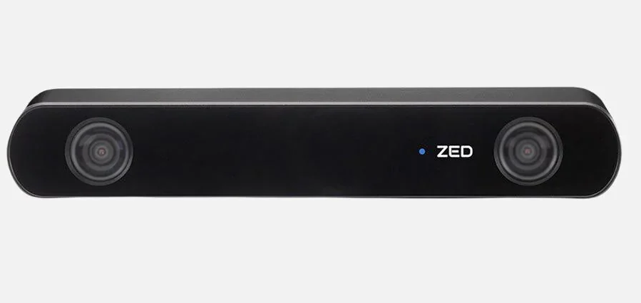
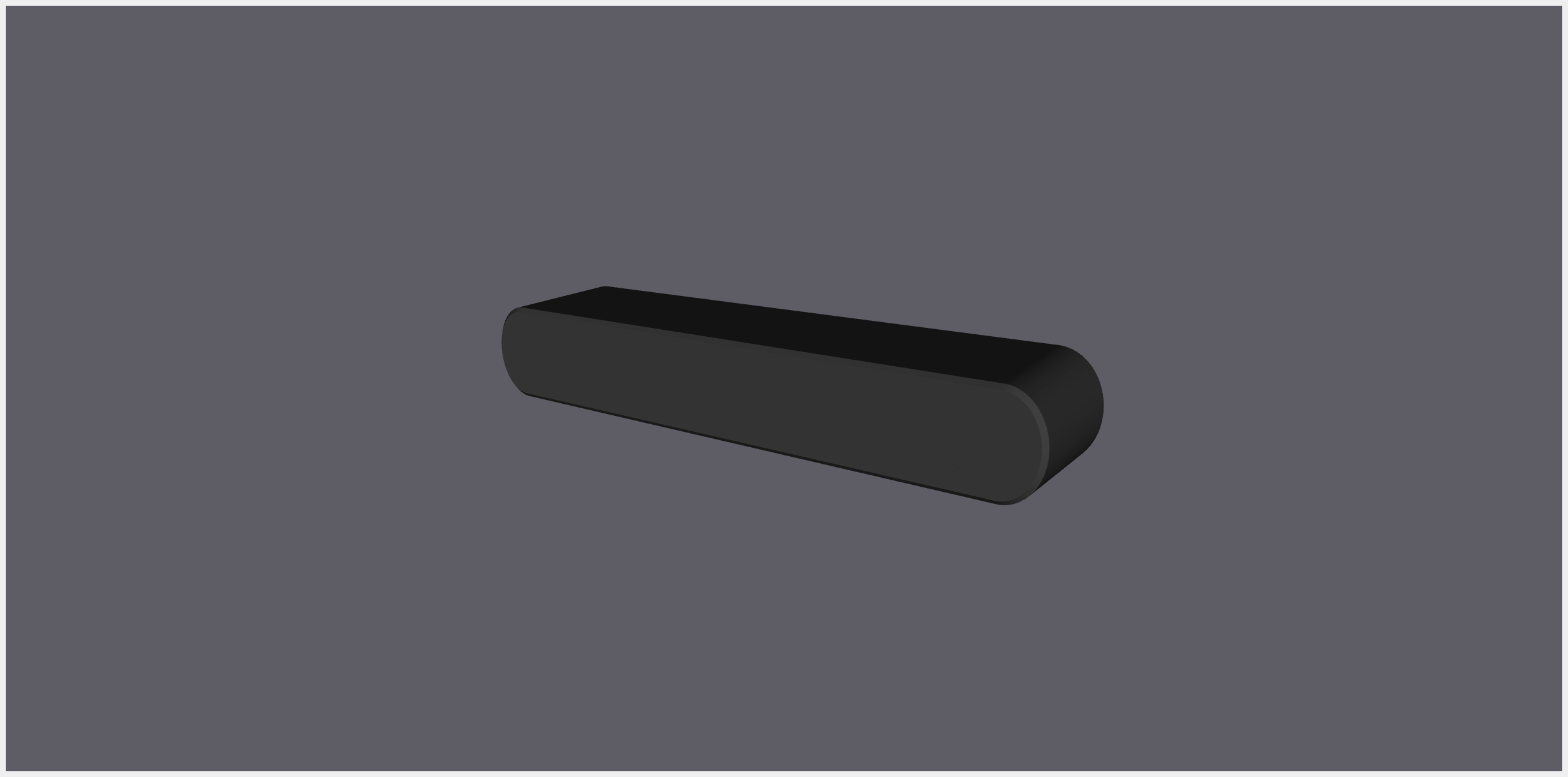
Source: ZED 2i Stereo Camera | StereoLabs Store | StereoLabs
The short route
StereoLabs, the manufacturer of ZED 2i along with other series of the stereo-camera products, has already released the official ROS 2 description packages ready for visualization, which is another bonus point why I chose their product.
The following steps are suitable if you only want to evaluate and check how the camera you purchase is doing. Our aim is to run the display_ed_cam_launch.py under the zed-ros2-examples package as it loads in the camera’s model from the official URDF file. Let’s see how this is done.
Instsall zed-ros2-wrapper
There is no debian available so we goota install the package in our own ROS 2 workspace.
cd <path/to/your>/ros2_ws/src
git clone https://github.com/stereolabs/zed-ros2-wrapper.git
# or for those who set up the SSH protocol
git clone git@github.com:stereolabs/zed-ros2-wrapper.git

cd ..
sudo apt update
rosdep update
rosdep install --from-paths src --ignore-src -r -y # install dependencies
colcon build --symlink-install --cmake-args=-DCMAKE_BUILD_TYPE=Release --parallel-workers $(nproc) # build the workspace
echo source $(pwd)/install/local_setup.bash >> ~/.bashrc # automatically source the installation in every new bash (optional)
source ~/.bashrc
For further detail on the installtion, please refer to the repository’s README.
Install zed-ros2-examples
Similarly, the zed-ros2-examples package has no Debian ready to install and we have to build it from source:
cd <path/to/your>/ros2_ws/src
git clone https://github.com/stereolabs/zed-ros2-examples.git
# or for those who has the SSH set up
git clone git@github.com:stereolabs/zed-ros2-examples.git

cd ..
sudo apt update
rosdep install --from-paths src --ignore-src -r -y
colcon build --symlink-install --cmake-args=-DCMAKE_BUILD_TYPE=Release
source ~/.bashrc
And now we are ready to bring up the camera. Connect the camera to your computer and on insert the command on the terminal:
ros2 launch zed_display_rviz2 display_zed_cam.launch.py camera_model:=<camera_model>
Replace <camera_model> with the model of the camera you are using. In this case, we simply replace with zed2i, i.e.
ros2 launch zed_display_rviz2 display_zed_cam.launch.py camera_model:=zed2i
Voila.
Source: https://github.com/stereolabs/zed-ros2-examples/tree/master/zed_display_rviz2
We can also integrate the camra model into our URDF file. For instance, If I already have a robot model in the URDF file, then I can simply add the following:
<?xml version="1.0"?>
<robot name="my_robot" xmlns:xacro="http://ros.org/wiki/xacro">
  <xacro:property name="mesh_dir" value="meshes" />
  <xacro:property name="robotname" value="my_robot" />
  <xacro:property name="M_PI" value="3.1415926535897931" />

  <!-- ZED 2i parameters -->
  <xacro:arg name="camera_name"   default="zed2i" />
  <xacro:arg name="camera_model"  default="zed2i" />
  <xacro:arg name="use_zed_localization" default="false" />
  <xacro:arg name="custom_baseline"  default="0.0" />
  <xacro:arg name="enable_gnss"   default="false" />
  <xacro:arg name="joint_x" default="0.1"/>
  <xacro:arg name="joint_y" default="0.0"/>
  <xacro:arg name="joint_z" default="0.1"/>

  <!-- The most barebone definition of the robot chasis just for reference-->
  <link name="${robotname}_base_link">
      <origin xyz="-0.017 -0.101 0.017" rpy="0 0 0"/>
  </link>

  <!-- The description of other robot parts -->


  <!-- ZED2i -->
  <xacro:include filename="$(find zed_wrapper)/urdf/zed_macro.urdf.xacro" />
  <xacro:zed_camera name="$(arg camera_name)" model="$(arg camera_model)" custom_baseline="$(arg custom_baseline)" enable_gnss="$(arg enable_gnss)">
	    <origin xyz="0.1 0.0 0.0" rpy="0 0 0"/>
  </xacro:zed_camera>

  <!-- Add a joint to connect the ZED Camera to the robot -->
  <xacro:if value="$(arg use_zed_localization)">
    <!-- ZED Localization -> The reference link is '$(arg camera_name)_camera_link' and 'base_link' is a child -->
    <joint name="$(arg camera_name)_joint" type="fixed">
      <parent link="$(arg camera_name)_camera_link"/>
      <child link="${robotname}_base_link"/>
      <origin
        xyz="$(arg joint_x) $(arg joint_y) $(arg joint_z)"
        rpy="0 0 0"
      />
    </joint>
  </xacro:if>
  <xacro:unless value="$(arg use_zed_localization)">
    <!-- NO ZED Localization -> '$(arg camera_name)_camera_link' is a child of 'base_link' -->
    <joint name="$(arg camera_name)_joint" type="fixed">
      <parent link="${robotname}_base_link"/>
      <child link="$(arg camera_name)_camera_link"/>
      <origin
        xyz="$(arg joint_x) $(arg joint_y) $(arg joint_z)"
        rpy="0 0 0"
      />
    </joint>
  </xacro:unless>
</robot>
As we can see the lines:
<xacro:include filename="$(find zed_wrapper)/urdf/zed_macro.urdf.xacro" />
<xacro:zed_camera name="$(arg camera_name)" model="$(arg camera_model)" custom_baseline="$(arg custom_baseline)" enable_gnss="$(arg enable_gnss)">
    <origin xyz="0.1 0.0 0.0" rpy="0 0 0"/>
</xacro:zed_camera>
we need to make sure $(find zed_wrapper) works correctly, as it retrieves the camera’s URDF.
The longer route but more customization
Since we already have the camera model and driver up and running, we should also be able to isolate the camera’s simulation model from the zed-wrapper such that from here on out we do not need satisfy any ZED driver’s dependency before being able to bring up the camera model on its own.
How about we ceate a standalone package for the ZED2i camera alone? First. Let create a zed2i_ros2_description package. And do not worry, you can find the full source code in my zed2i_ros2_description GitHub repository if you don’t know what to do next.
Create your own zed2i_ros2_description package as such:
cd <path/to/your>/ros2_Ws/src
ros2 pkg create --build-type ament_cmake zed2i_ros2_description
Let’s build the package first to ensure it can be found by the system.
cd <path/to/your>/ros2_Ws
colcon build --packages-select zed2i_ros2_description
source ~/.bashrc
Now under the package directory you just created, mkdir the following diretories: meshes/, model/, launch/. Once these directories are created, in the root CMakeLists.txt of the package add the following lines:
install(
  DIRECTORY launch meshes model
  DESTINATION share/${PROJECT_NAME}
)
Go to the root directory of the ROS 2 workspace and build the package again. Now you have the description package opened for business.
Place the necessary assets
Since mesh rendering is optional, we can first compose our URDF file and see if the TF tree can be created by the robot_state_publisher and joint_State_publisher. Under the directory model/, touch a new URDF file: zed2i_urdf.xacro. Paste the following content in this file as shown below. By the way, I extracted and composed these codes from the official zed-ros2-wrapper package. Thank me later!
<?xml version="1.0"?>

<!--
// Copyright 2022 Stereolabs
//
// Licensed under the Apache License, Version 2.0 (the "License");
// you may not use this file except in compliance with the License.
// You may obtain a copy of the License at
//
//      http://www.apache.org/licenses/LICENSE-2.0
//
// Unless required by applicable law or agreed to in writing, software
// distributed under the License is distributed on an "AS IS" BASIS,
// WITHOUT WARRANTIES OR CONDITIONS OF ANY KIND, either express or implied.
// See the License for the specific language governing permissions and
// limitations under the License.
-->

<robot name="stereolabs_camera" xmlns:xacro="http://ros.org/wiki/xacro">
    <xacro:property name="M_PI"     value="3.1415926535897931" />

    <xacro:arg name="camera_name"   default="zed2i" />
    <xacro:arg name="camera_model"  default="zed2i" />
    <xacro:arg name="custom_baseline"  default="0.0" />
    <!-- If GNSS fusion is enabled the position of the antenna with respect to the camera mount point is required -->
    <xacro:arg name="enable_gnss"   default="false" />
    <xacro:arg name="gnss_x" default="0.0" />
    <xacro:arg name="gnss_y" default="0.0" />
    <xacro:arg name="gnss_z" default="0.0" />

    <xacro:property name="baseline" value="0.12" />
    <xacro:property name="height" value="0.03" />
    <xacro:property name="bottom_slope" value="0.0" />
    <xacro:property name="screw_offset_x" value="-0.01" />
    <xacro:property name="screw_offset_z" value="0.0" />
    <xacro:property name="optical_offset_x" value="-0.01" />

    <!-- Camera mounting point (the threaded screw hole in the bottom) -->
    <link name="$(arg camera_name)_camera_link" />

    <!-- Camera Center -->
    <link name="$(arg camera_name)_camera_center">
        <visual>
            <origin xyz="${screw_offset_x} 0 ${screw_offset_z}" rpy="0 0 0"/>
        </visual>
        <collision>
            <origin xyz="${screw_offset_x} 0 ${screw_offset_z}" rpy="0 0 0"/>
        </collision>
    </link>
    <joint name="$(arg camera_name)_camera_center_joint" type="fixed">
      <parent link="$(arg camera_name)_camera_link"/>
      <child link="$(arg camera_name)_camera_center"/>
      <origin xyz="0 0 ${height/2}" rpy="0 ${bottom_slope} 0" />
    </joint>


    <!-- Left Camera -->
    <link name="$(arg camera_name)_left_camera_frame">
    </link>
    <joint name="$(arg camera_name)_left_camera_joint" type="fixed">
        <parent link="$(arg camera_name)_camera_center"/>
        <child link="$(arg camera_name)_left_camera_frame"/>
        <origin xyz="${optical_offset_x} ${baseline/2} 0" rpy="0 0 0" />
    </joint>

    <link name="$(arg camera_name)_left_camera_optical_frame"/>
    <joint name="$(arg camera_name)_left_camera_optical_joint" type="fixed">
        <origin xyz="0 0 0" rpy="-${M_PI/2} 0.0 -${M_PI/2}"/>
        <parent link="$(arg camera_name)_left_camera_frame"/>
        <child link="$(arg camera_name)_left_camera_optical_frame"/>
    </joint>


    <!-- Right Camera -->
    <link name="$(arg camera_name)_right_camera_frame">
    </link>
    <joint name="$(arg camera_name)_right_camera_joint" type="fixed">
        <parent link="$(arg camera_name)_camera_center"/>
        <child link="$(arg camera_name)_right_camera_frame"/>
        <origin xyz="${optical_offset_x} -${baseline/2} 0" rpy="0 0 0" />
    </joint>

    <link name="$(arg camera_name)_right_camera_optical_frame"/>
    <joint name="$(arg camera_name)_right_camera_optical_joint" type="fixed">
        <origin xyz="0 0 0" rpy="-${M_PI/2} 0.0 -${M_PI/2}"/>
        <parent link="$(arg camera_name)_right_camera_frame"/>
        <child link="$(arg camera_name)_right_camera_optical_frame"/>
    </joint>

    <xacro:if value="$(arg enable_gnss)">
      <link name="$(arg camera_name)_gnss_link" />
      <joint name="$(arg camera_name)_gnss_joint" type="fixed">
        <parent link="$(arg camera_name)_camera_link"/>
        <child link="$(arg camera_name)_gnss_link"/>
        <xacro:insert_block name="gnss_origin" />
      </joint>
    </xacro:if>

</robot>
And under the same directory, also add a new new file to specify the color of the materials: materials.urdf.xacro and paste the following content:
<?xml version="1.0"?>

<!--
// Copyright 2022 Stereolabs
//
// Licensed under the Apache License, Version 2.0 (the "License");
// you may not use this file except in compliance with the License.
// You may obtain a copy of the License at
//
//      http://www.apache.org/licenses/LICENSE-2.0
//
// Unless required by applicable law or agreed to in writing, software
// distributed under the License is distributed on an "AS IS" BASIS,
// WITHOUT WARRANTIES OR CONDITIONS OF ANY KIND, either express or implied.
// See the License for the specific language governing permissions and
// limitations under the License.
-->

<robot>
    <material name="zed_mat">
        <color rgba="0.8 0.8 0.8 1.0"/>
    </material>
    <material name="zedm_mat">
        <color rgba="0 0 0 1.0"/>
    </material>
    <material name="zed2_mat">
        <color rgba="0.25 0.25 0.25 1.0"/>
    </material>
    <material name="zed2i_mat">
        <color rgba="0.25 0.25 0.25 1.0"/>
    </material>
    <material name="zedx_mat">
        <color rgba="0.25 0.25 0.25 1.0"/>
    </material>
    <material name="zedxm_mat">
        <color rgba="0.25 0.25 0.25 1.0"/>
    </material>
    <material name="virtual_mat">
        <color rgba="0.25 0.25 0.25 1.0"/>
    </material>
</robot>
Now, let’s place the STL file into the package. If you happen to have zed-ros2-wrapper package around, you can find the official STL fle under the path zed-ros2-wrapper/zed-ros2-interfaces/meshes. Copy the STL file and place it under your package under the meshes/ directory.
Now head back to model/zed2i_urdf.xacro and the following lines within the <geometry> element, like such:
<robot name="stereolabs_camera" xmlns:xacro="http://ros.org/wiki/xacro">
<!-- Under the robot element, place the following line -->
  <xacro:property name="zed2i_mesh" value="package://zed2i_ros2_description/meshes/zed2i.stl" />

  <!-- Move down the document, look for the link = $(arg camera_name)_camera_center element -->
  <!-- and add the "geometry" element under both visual and collision element and   -->
  <!-- within "geometry" the "mesh" element to specify the STL file -->
  <link name="$(arg camera_name)_camera_center">
      <visual>
          <origin xyz="${screw_offset_x} 0 ${screw_offset_z}" rpy="0 0 0"/>
          <geometry>
              <mesh filename="package://zed2i_ros2_description/meshes/zed2i.stl" />
          </geometry>
      </visual>
      <collision>
          <origin xyz="${screw_offset_x} 0 ${screw_offset_z}" rpy="0 0 0"/>
          <geometry>
              <mesh filename="package://zed2i_ros2_description/meshes/zed2i.stl" />
          </geometry>
      </collision>
  </link>

  <!--  -->
You also want to specify the color of the whole camera model. In the same file, add the following lines:
<robot name="stereolabs_camera" xmlns:xacro="http://ros.org/wiki/xacro">
<!-- Similrly, you want to load in the material file you just created -->
    <xacro:include filename="$(find zed2i_ros2_description)/model/materials.urdf.xacro" />

    <link name="$(arg camera_name)_camera_center">
    <!-- Camera Center -->
    <link name="$(arg camera_name)_camera_center">
        <visual>
            <origin xyz="${screw_offset_x} 0 ${screw_offset_z}" rpy="0 0 0"/>
            <geometry>
                <mesh filename="package://zed2i_ros2_description/meshes/zed2i.stl" />
            </geometry>
            <!-- Add the material color RIGHT HERE -->
            <material name="$(arg camera_model)_mat" />
        </visual>
        <collision>
            <origin xyz="${screw_offset_x} 0 ${screw_offset_z}" rpy="0 0 0"/>
            <geometry>
                <mesh filename="package://zed2i_ros2_description/meshes/zed2i.stl" />
            </geometry>
        </collision>
    </link>
So the whole URDF file would look like this:
<?xml version="1.0"?>

<!--
// Copyright 2022 Stereolabs
//
// Licensed under the Apache License, Version 2.0 (the "License");
// you may not use this file except in compliance with the License.
// You may obtain a copy of the License at
//
//      http://www.apache.org/licenses/LICENSE-2.0
//
// Unless required by applicable law or agreed to in writing, software
// distributed under the License is distributed on an "AS IS" BASIS,
// WITHOUT WARRANTIES OR CONDITIONS OF ANY KIND, either express or implied.
// See the License for the specific language governing permissions and
// limitations under the License.
-->

<robot name="stereolabs_camera" xmlns:xacro="http://ros.org/wiki/xacro">
    <xacro:include filename="$(find zed2i_ros2_description)/model/materials.urdf.xacro" />

    <xacro:property name="M_PI"     value="3.1415926535897931" />
    <xacro:property name="zed2i_mesh" value="package://zed2i_ros2_description/meshes/zed2i.stl" />

    <xacro:arg name="camera_name"   default="zed2i" />
    <xacro:arg name="camera_model"  default="zed2i" />
    <xacro:arg name="custom_baseline"  default="0.0" />
    <!-- If GNSS fusion is enabled the position of the antenna with respect to the camera mount point is required -->
    <xacro:arg name="enable_gnss"   default="false" />
    <xacro:arg name="gnss_x" default="0.0" />
    <xacro:arg name="gnss_y" default="0.0" />
    <xacro:arg name="gnss_z" default="0.0" />

    <xacro:property name="baseline" value="0.12" />
    <xacro:property name="height" value="0.03" />
    <xacro:property name="bottom_slope" value="0.0" />
    <xacro:property name="screw_offset_x" value="-0.01" />
    <xacro:property name="screw_offset_z" value="0.0" />
    <xacro:property name="optical_offset_x" value="-0.01" />

    <!-- Camera mounting point (the threaded screw hole in the bottom) -->
    <link name="$(arg camera_name)_camera_link" />

    <!-- Camera Center -->
    <link name="$(arg camera_name)_camera_center">
        <visual>
            <origin xyz="${screw_offset_x} 0 ${screw_offset_z}" rpy="0 0 0"/>
            <geometry>
                <mesh filename="package://zed2i_ros2_description/meshes/zed2i.stl" />
            </geometry>
            <material name="$(arg camera_model)_mat" />
        </visual>
        <collision>
            <origin xyz="${screw_offset_x} 0 ${screw_offset_z}" rpy="0 0 0"/>
            <geometry>
                <mesh filename="package://zed2i_ros2_description/meshes/zed2i.stl" />
            </geometry>
        </collision>
    </link>
    <joint name="$(arg camera_name)_camera_center_joint" type="fixed">
      <parent link="$(arg camera_name)_camera_link"/>
      <child link="$(arg camera_name)_camera_center"/>
      <origin xyz="0 0 ${height/2}" rpy="0 ${bottom_slope} 0" />
    </joint>


    <!-- Left Camera -->
    <link name="$(arg camera_name)_left_camera_frame">
    </link>
    <joint name="$(arg camera_name)_left_camera_joint" type="fixed">
        <parent link="$(arg camera_name)_camera_center"/>
        <child link="$(arg camera_name)_left_camera_frame"/>
        <origin xyz="${optical_offset_x} ${baseline/2} 0" rpy="0 0 0" />
    </joint>

    <link name="$(arg camera_name)_left_camera_optical_frame"/>
    <joint name="$(arg camera_name)_left_camera_optical_joint" type="fixed">
        <origin xyz="0 0 0" rpy="-${M_PI/2} 0.0 -${M_PI/2}"/>
        <parent link="$(arg camera_name)_left_camera_frame"/>
        <child link="$(arg camera_name)_left_camera_optical_frame"/>
    </joint>


    <!-- Right Camera -->
    <link name="$(arg camera_name)_right_camera_frame">
    </link>
    <joint name="$(arg camera_name)_right_camera_joint" type="fixed">
        <parent link="$(arg camera_name)_camera_center"/>
        <child link="$(arg camera_name)_right_camera_frame"/>
        <origin xyz="${optical_offset_x} -${baseline/2} 0" rpy="0 0 0" />
    </joint>

    <link name="$(arg camera_name)_right_camera_optical_frame"/>
    <joint name="$(arg camera_name)_right_camera_optical_joint" type="fixed">
        <origin xyz="0 0 0" rpy="-${M_PI/2} 0.0 -${M_PI/2}"/>
        <parent link="$(arg camera_name)_right_camera_frame"/>
        <child link="$(arg camera_name)_right_camera_optical_frame"/>
    </joint>

    <xacro:if value="$(arg enable_gnss)">
      <link name="$(arg camera_name)_gnss_link" />
      <joint name="$(arg camera_name)_gnss_joint" type="fixed">
        <parent link="$(arg camera_name)_camera_link"/>
        <child link="$(arg camera_name)_gnss_link"/>
        <xacro:insert_block name="gnss_origin" />
      </joint>
    </xacro:if>

</robot>
Set up the launch file
We are almost done so hang in there. Similar to how we set up the LiDAR description launch file, the one for ZED 2i is almost identical. Let’s name this launch file as ros2 launch zed2i_ros2_description zed_camera.launch.py and paste the following content in it:
#!/usr/bin/env python3

from pathlib import Path
from launch import LaunchDescription
from launch.substitutions import Command
from launch_ros.actions import Node
from launch_ros.substitutions import FindPackageShare

def generate_launch_description():
    pkg_path = FindPackageShare('zed2i_ros2_description').find('zed2i_ros2_description')
    xacro_file_path = f'{pkg_path}/model/zed2i_urdf.xacro'

    assert Path(xacro_file_path).exists(), f'URDF file not found at {xacro_file_path}'
    assert Path(xacro_file_path).is_file(), f'URDF file {xacro_file_path} is NOT a file'

    print(f'Reading xacro file: {xacro_file_path}')

    task_queue = []

    task_queue.append(
        Node(
            package='robot_state_publisher',
            executable='robot_state_publisher',
            name='robot_state_publisher',
            output='screen',
            parameters=[{'robot_description': Command(['xacro ', xacro_file_path])}],
        )
    )

    task_queue.append(
        Node(
            package='joint_state_publisher',
            executable='joint_state_publisher',
            name='joint_state_publisher',
            output="screen"
        )
    )

    task_queue.append(
        Node(
            package='rviz2',
            executable='rviz2',
            name='rviz2'
        )
    )

    return LaunchDescription(task_queue)
With this launch file saved, head to the root directory of the workspace, and build the package again.
Fire it up
Let’s run the launch file to load in the model. Use the following command:
ros2 launch zed2i_ros2_description zed_camera.launch.py
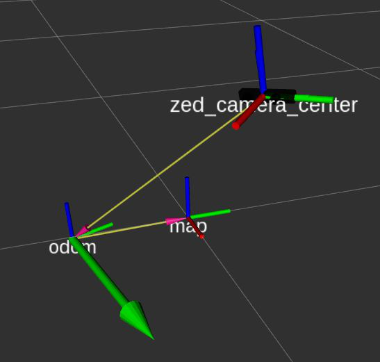
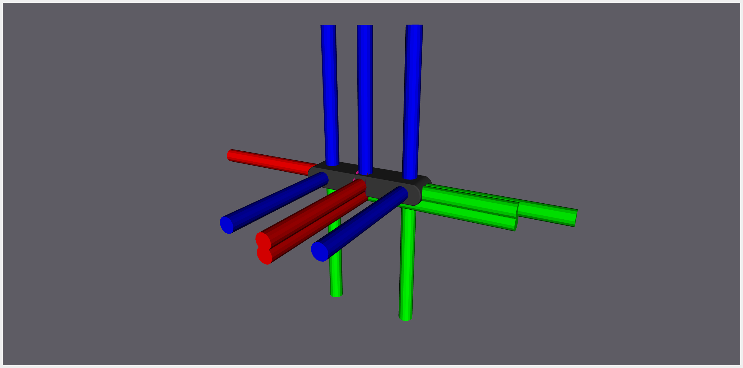
Rviz2 will be brought up. Before you can actually anything, In the “Displays” panel on the left, look for the “Global options” category and expand the drop-down menu “Fixed frame”. The drop-down menu shows the list of available TF frame. Let’s choose the “zed2i_cmaera_center” frame.
Next, head down to the bottom-left of the Rviz2 window, click open “Add” and in the pop-up window, scroll down to double-click on “TF”. You may see the TF tree appear in Rviz2.
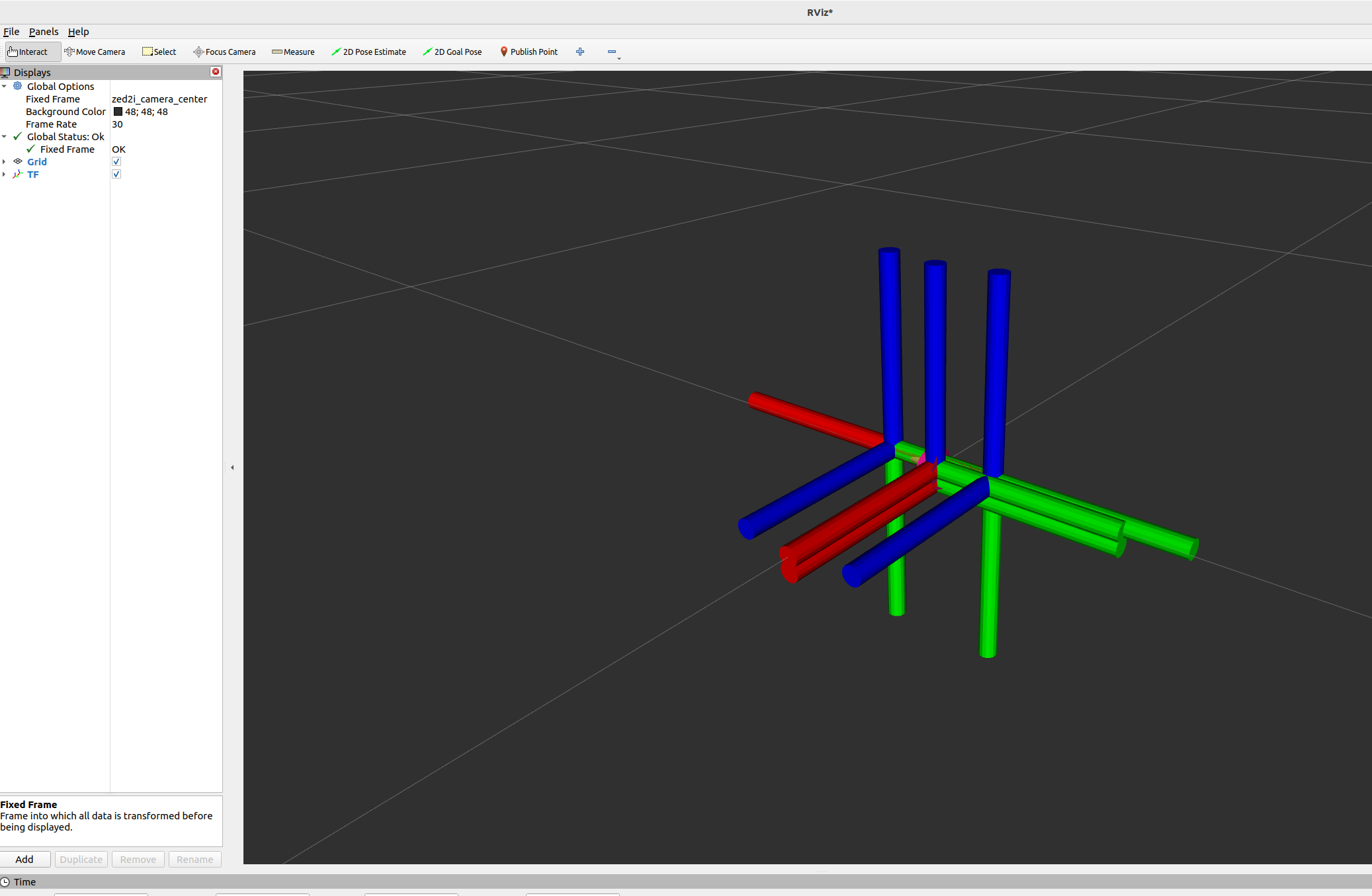
Once again click “Add” and in the pop-up window select “RobotModel”. Expand the RobotModel category in the Displays panel. Notice there is a expandable category “Description topic”. Click on it, you may see a drop-down menu appears on the right. Click on the drop-down menu and select /robot_description. This way Rviz2 knows where to look for the description that we painstakingly loaded in.

The model should appear alongside the TF tree (actually zoom in to take a better look).
If you want to toggle off the TF tree to have a cleaner look of the robot model, check-off the “TF” category on the Displays panel.
Conclusion
In this article, we noticed that SereoLabs, the company behind ZED 2i and its sister products, has curated a series of off-the-shelf solutions to set up the camera model along with its driver such that the customers do not have to write their own codes from scratch. With the available toolsets, we go over how to integrate the camera model into our own project.
On the other hand, we also have the option to extract the essential parts of the camera model and create own own description, hence the latter half of this article we discussed how to set up the major files to successfumy lly load in the camera model into Rviz2. The implementation can also be found in my GitHub repository: Megacephalo/zed2i_ros2_description.
References
[1] https://www.stereolabs.com/docs/ros2/030_rviz2
[2] https://github.com/stereolabs/zed-ros2-examples
[3] https://github.com/stereolabs/zed-ros2-wrapper/
[4] https://github.com/stereolabs/zed-ros2-examples/tree/master/zed_display_rviz2