Build the Unitree LiDAR L1 Simulation Model from scratch
This article belongs to the series “Create Sphero RVR+ simulation model” and will walk you through creating your own Unitree L1 LiDAR.
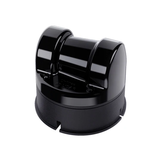
Source: Unitree 4D LiDAR L1 - Unitree Robotics
Create the simulation model for Unitree L1 LiDAR
Let’s create a ROS 2 description for the LiDAR. I recommend creating a C++ package:
cd <path/to/your>/ros2_ws/src

ros2 pkg create --build-type ament_cmake unitree_lidar_description
Remember to replace to your actual workspace path.
Let’s build the package first to make sure that it can be built and successfully added to the ROS system data structure:
cd <path/to/your>/ros2_ws    # back to the root directory of your ROS 2 workspace
colcon build
source <path/to/your>/ros2_ws/install/setup.bash
We calle our package unitree_lidar_description. Within the package let’s create two new directories: launch, meshes and model.
In CMakeLists.txt make sure the following lines are uncommented:
install(
  DIRECTORY launch meshes model
  DESTINATION share/${PROJECT_NAME}
)
such that the files under these directoies are installed and can be found by the ROS system.
Let’s cd into the model directory, create a file unilidar_l1.urdf.xacro. Within the Xacro file, paste the following:
<?xml version="1.0"?>
<robot name="unlidar_l1" xmlns:xacro="http://wiki.ros.org/xacro">

<link name="unilidar_lidar">
    <visual>
        <origin xyz="0 0 0" rpy="0 0 0"/>
    </visual>
    <collision>
        <origin xyz="0 0 0" rpy="0 0 0"/>
    </collision>
    <inertial>
        <mass value="0.5"/>
        <origin xyz="0 0 0" rpy="0 0 0"/>
        <inertia ixx="0.001" ixy="0.0" ixz="0.0" iyy="0.001" iyz="0.0" izz="0.001"/>
    </inertial>
</link>

<link name="unlidar_imu">
    <collision>
        <geometry>
            <box size="0.05 0.05 0.05"/>
        </geometry>
        <origin xyz="0 0 0" rpy="0 0 0"/>
    </collision>
    <inertial>
        <mass value="0.5"/>
        <origin xyz="0 0 0" rpy="0 0 0"/>
        <inertia ixx="0.001" ixy="0.0" ixz="0.0" iyy="0.001" iyz="0.0" izz="0.001"/>
    </inertial>
</link>
<joint name="unilidar_imu_joint" type="fixed">
    <parent link="unilidar_lidar"/>
    <child link="unlidar_imu"/>
    <origin xyz="0.0 0.0 0.0" rpy="0 0 0"/>
</joint>

</robot>
Within this script, we created a “robot” called unlidar_l1. The robot contains one two frames: unilidar_lidar and unlidar_imu in which the latter is the child node of the former frame. Both edges are associated with a joint unilidar_imu_joint. Within each frame, we can see that the visual, collision, and the inertial are defined. Within the <joint> element, the parent, child, and the spatial relationship of the joint from the parent to the child frames are defined.
At this point, you can already play with the model as its overall reference frame relationship is defined, but we want to go one extra mile.
Specify the mesh
Since we need either the STL or COLLADA file to define the meshes, we can either find an already available mesh file to load in our existing URDF, or we can find a STEP file containing the CAD object, and then extract the “skin” out of it with your favorite CAD software.
Fortunately, an official CAD file is provided by Unitree. Please visit the page Download Center L1 - Unitree Robotics and click on Download link for the L1 3D Model.
Once the STEP file is downloaded, open it with your favorite CAD software. I am using FreeCAD to help me export the sensor CAD body into its STL file. I named my STL file as unilidar_l1_mesh.stl. Place the STL file under the meshes directory that we just created in our ROS 2 description package.
Now head back to the xacro file we just edited, add the line under the <robot> element
<xacro:property name="unilidar_mesh" value="package://unitree_lidar_description/meshes/unilidar_l1_mesh.stl" />
and add this line:
<mesh filename="${unilidar_mesh}" scale="0.001 0.001 0.001"/>
within the <visual>/><geometry> and <collision>/<geometry> elements.
Although we will load the model mesh but it still lacks color. We can define our color by creating a new document named materials.urdf under the model directory, where the unilidar_l1.urdf.xacro lives to facilitate file referencing. We are defining the color RGB codes within this materials.urdf:
<?xml version="1.0"?>
<robot>
  <material name="White">
    <color rgba="1 1 1 1.0"/>
  </material>

  <material name="DarkGrey">
    <color rgba="0.3 0.3 0.3 1.0"/>
  </material>

  <material name="LightGrey">
    <color rgba="0.8 0.8 0.8 1.0"/>
  </material>

  <material name="Black">
    <color rgba="0 0 0 1.0"/>
  </material>

  <material name="Grey">
    <color rgba="0.7 0.7 0.7 1.0"/>
  </material>

  <material name="Blue">
    <color rgba="0.0 0.0 0.8 1.0"/>
  </material>

</robot>
Let’s specify the color of the sensor by adding the second property under the <robot> element:
<xacro:include filename="$(find unitree_lidar_description)/model/materials.urdf"/>
Notice that the $(find ...) is a handy syntax to automatically acquire the abslute path to the package in the install/.../<package> directory.
We want to color the whole sensor in dark gray, so let’s add the following line under the <visual> element:
<material name="DarkGrey"/>
Now, the whole unilidar_l1.urdf.xacro will look like this:
<?xml version="1.0"?>
<robot name="unlidar_l1" xmlns:xacro="http://wiki.ros.org/xacro">

<xacro:property name="unilidar_mesh" value="package://unitree_lidar_description/meshes/unilidar_l1_mesh.stl" />

<xacro:include filename="$(find unitree_lidar_description)/model/materials.urdf"/>

<link name="unilidar_lidar">
    <visual>
        <geometry>
            <mesh filename="${unilidar_mesh}" scale="0.001 0.001 0.001"/>

        </geometry>
        <material name="DarkGrey"/>
        <origin xyz="0 0 0" rpy="0 0 0"/>
    </visual>
    <collision>
        <geometry>
            <mesh filename="${unilidar_mesh}" scale="0.001 0.001 0.001"/>
        </geometry>
        <origin xyz="0 0 0" rpy="0 0 0"/>
    </collision>
    <inertial>
        <mass value="0.5"/>
        <origin xyz="0 0 0" rpy="0 0 0"/>
        <inertia ixx="0.001" ixy="0.0" ixz="0.0" iyy="0.001" iyz="0.0" izz="0.001"/>
    </inertial>
</link>

<link name="unlidar_imu">
    <collision>
        <geometry>
            <box size="0.05 0.05 0.05"/>
        </geometry>
        <origin xyz="0 0 0" rpy="0 0 0"/>
    </collision>
    <inertial>
        <mass value="0.5"/>
        <origin xyz="0 0 0" rpy="0 0 0"/>
        <inertia ixx="0.001" ixy="0.0" ixz="0.0" iyy="0.001" iyz="0.0" izz="0.001"/>
    </inertial>
</link>
<joint name="unilidar_imu_joint" type="fixed">
    <parent link="unilidar_lidar"/>
    <child link="unlidar_imu"/>
    <origin xyz="0.0 0.0 0.0" rpy="0 0 0"/>
</joint>

</robot>
Automate the model generation from the URDF file with launch file
Now let’s use a handy launch file to load the URDF into the robot_state_publisher. First cd under the launch directory create the new launch file unilidar_l1.launch.py. Within the launch file, paste the following contnt:
#!/usr/bin/env python3

from pathlib import Path
from launch import LaunchDescription
from launch.actions import DeclareLaunchArgument
from launch.substitutions import Command, LaunchConfiguration
from launch_ros.actions import Node
from launch_ros.substitutions import FindPackageShare

enable_rviz: bool = True

def generate_launch_description():
    pkg_path = FindPackageShare('unitree_lidar_description').find('unitree_lidar_description')
    xacro_file_path = f'{pkg_path}/model/unilidar_l1.urdf.xacro'

    assert Path(xacro_file_path).exists(), f'URDF file not found at {xacro_file_path}'
    assert Path(xacro_file_path).is_file(), f'URDF file {xacro_file_path} is NOT a file'

    print(f'Reading xacro file: {xacro_file_path}')

    task_queue = []

    task_queue.append(
        Node(
            package='robot_state_publisher',
            executable='robot_state_publisher',
            name='robot_state_publisher',
            output='screen',
            parameters=[{'robot_description': Command(['xacro ', xacro_file_path])}],
        )
    )

    task_queue.append(
        Node(
            package='joint_state_publisher',
            executable='joint_state_publisher',
            name='joint_state_publisher',
            output="screen"
        )
    )

    if enable_rviz:
        rviz2_node = Node(
            package='rviz2',
            executable='rviz2',
            name='rviz2',
            output='screen'
        )
        task_queue.append(rviz2_node)

    return LaunchDescription(task_queue)
The xacro_file_path paramter holds the path to our URDF file. This file is given to the robot_state_publisher to generate the 3D model. Once joint_state_publisher also join in, we can visualize the model in the visualizer - Rviz2.
Let’s fire it up
Now we can run the launch file and check if the lidar TF tree and model is generated. First, build the package
cd <path/to/your>/ros_ws
colcon build
# Or specify to build just this pacakge
colcon build --packages-select unitree_lidar_description
Make sure to either manuall source <path/to/your>/ros2_ws/install/local_setup.bash or have it already saved in ~/.bashrc. At this point I assume that the ROS system can successfully find where this package is.
ros2 launch unitree_lidar_description unilidar_l1.launch.py
and you shall find:
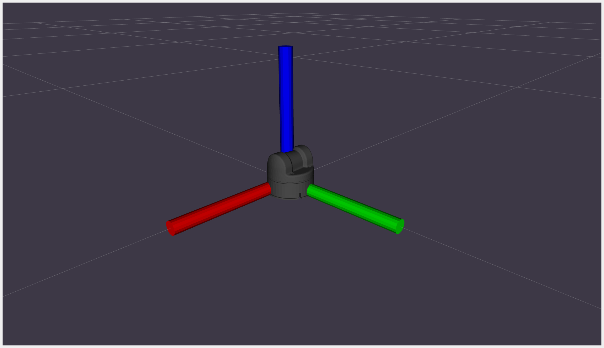
Conclusion
In this tutorial you learned how to compose a ROS 2 description package, create the URDF script to specify the TF, collision, and visual models, add the mesh to make the simulation more realistic, and eventually fire up the launch file to load the URDF file into robot_state_pbulsiher and joint_state_publisher to render the 3D model. Eventually, you able to visualize the LiDAR model in Rviz2.